


Power analysis is a specific kind of side-channel analysis performed on the power consumption of a target device. This technique can be applied for various purposes and are mostly known for their application in cryptographic attacks.
However, power analysis can be useful in many other cases and can be performed with simple and inexpensive tools.
Power consumption principle
All active components consume a certain amount of power in order to work properly. This power consumption is due to the fact that the transistors inside of the component do need some power to switch from one state to the other. The more transistors you have to switch the more power you will consume. Looking at a step above, each logic gate will consume more power if it needs to switch state. One step higher again and the whole instruction a CPU executes might take more power depending on its input.
This is the (simplified) basic principle behind the power analysis methods we will cover here: The CPU will consume more or less power depending on the type of operation it will do.
The power(


Where
Note that this is not fully accurate, there are way more variables involved when calculating the power consumption of a MCU (see this post for more information). But it is enough to understand the basics of power analysis.
Since most of the time the DUT is powered with a fixed voltage, it means that we have to find a way to measure the current drawn by the target device to measure its power consumption.
Measuring current
Now that we know that we have to measure the current to deduce the power consumption, let’s see how we can actually read these values. There are many ways to measure current in a circuit.
Multimeter
The easiest but impractical way to measure current is to use a multimeter in series with the DUT power source. This will correctly display the device power consumption, but it is not useful for an analyst as it only displays the actual consumption and does not allow to visualize the variations in a precise manner.
Current probe
The next possibility is to use an oscilloscope with a current probe. This kind of probe is really nice since it does not require to modify the circuit to be used. Just clip the probe around a cable and the oscilloscope is able to plot the current flowing through the cable.
This is the best solution, but the main problem is that even the cheapest probes cost more than a thousand dollars and can be much higher for more precise probes. The other drawback is that these probes have rather limited bandwidth (<200MHz) compared to other solutions.
Shunt resistor
For a hobbyist, putting thousands in a probe is not an option, so we need to find another way to use an oscilloscope to measure the current. Oscilloscopes usually measure voltage and not current, so how can we find a way to “convert” these two units? By using Ohm’s law

Where 
By using a fixed resistor within the circuit, it is possible to generate a voltage across the resistor that is proportionnal to the current. (Remember: the current varies because of the DUT, but the voltage stays constant).
Obviously, if the resistor generates a voltage drop, the DUT will also be impacted by the drop and might stop working properly, so the resistor value we need to use has to be :
- As small as possible to avoid a too important voltage drop
- Big enough so the oscilloscope will be able to “see” the variation
There is no perfect resistor value that works every time, but usually a resistor that is between 1 and 10 Ohms is fine for standard devices.
For even better results, the resistor tolerance should be as small as possible. The tolerance is the variation of the resistance value depending on the voltage and the ambient temperature and is displayed in the last colored ring.
This solution works really well in a lot of situations, and has the advantage of being really cheap at the cost of having to modify the circuit to include the resistor, which can sometimes be tedious. It still has the best price-to-performance ratio of the three presented solutions, so we’ll use this method for our test.
Differential probe
For the sake of completeness, there is a fourth option to measure power consumption, the use of a differential probe. This measures the voltage difference between two points in a circuit. It is usually coupled with a shunt resistor and provides a better measure than the passive probe along with a higher bandwidth compared to the current probe. This kind of probe is also relatively expensive.
Practical power consumption analysis
Let’s take a practical example to understand how it works. During the research I made on the security of SD cards (slides), I found that many cards are vulnerable to a timing attack on the password verification function. This timing attack can also be identified with the help of power analysis. Let’s see how it works.
Setup
The setup is really simple. An SD card is connected to a 3.3V power source and to an SPI interface for communication. I added a 10 Ohm resistor between the Vss pin and the ground to act as a shunt resistor and connected the oscilloscope probe to the resistor.

Note that the resistor could also be installed between the +3.3V and the Vdd pins of the SD card with the same results.
With the setup in place, we can see that the SD cards consumes some power when running the initialization commands:

That means that our setup works. Let’s try to replicate the timing attack, but by looking at the power consumption instead of the SPI. For this, we will use an SD card and lock it using the password “123456”.
Timing attack using power analysis
As seen during my SD card research, once the unlock command has been sent the card will first check if the length of the entered password matches the length of the correct password. It will then check every byte of the password until every byte matches. If any discrepancy is found during the process, the card will stop and reply directly.
Let’s first try to send an unlock request with a password length of 5 (bad length matching :
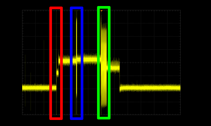
Here we can distinguish three main peaks in the card consumption:
- The set block length command (Red). This command sets the size of the data blocks we will send
- The LOCK_UNLOCK command (Blue) being processed. This command does not contain the password yet. It only tells the SD card that the next data block will contain the password to check
- The password verification and response sent by the card (Green). Here the password is being processed, and the card will send its response
If we zoom a little bit on the green part, we can see a short period of time where the card consumption is higher, then the card proceeds to send the response:

By zooming on this specific part and measuring several times, we can narrow down the password processing part to the one highlighted below :

Now we can set the password to “000000” (Correct length, incorrect first byte) :

The difference is not easy to catch here, using an animation is way easier :

So far so good, the power analysis can show a clear time difference between our attempts. This means that our power analysis worked! The last part of the attack is to instrument the oscilloscope to automate the trace acquisition and the trace analysis, which we won’t cover here.
As a side note, here is a screen capture made with a professional oscilloscope and a current probe so you can clearly see the advantages of such equipment when you need to perform an in-depth analysis :

The signal is much cleaner, and the consumption peak really stands out from the rest. The signal is also less noisy, which helps a lot when processing the data using scripts.
Conclusions
Power analysis is one example of side-channel that is used in security evaluations. This analysis can be used to uncover security vulnerabilities on embedded devices, such as the one shown in this post. It is also widely used in cryptographic attacks, where it allows us to retrieve the key used in an AES encryption for instance.
This quick introduction to power analysis shows that with a quite small budget it is possible to perform a power analysis on a target. As we’ve seen, it is also possible to tell when the DUT is performing some operations. This information can, for instance, be used to generate a glitch pulse at a specific time, when no other external trigger is available.

Interesting read, thank you Nicolas. Good to see that relatively simple and widely available equipment can be used for such sophisticated investigations. You mention it would also be possible to connect the shunt resistor between Vdd and +3.3V. I guess this would need a difference amplifier since the oscilloscope cannot be set to 200mV/div resolution with DC coupling on a 3.3V voltage rail.