


Reverse engineering a microcontroller firmware is sometimes a long and tedious task, but even a seasoned reverser might struggle to get their favorite tool to load the firmware correctly. Depending on the way the firmware has been retrieved, some crucial information might be missing, like the base flash address (which of course varies depending on the manufacturer or the chip family) or the RAM location in the memory map.
In this post, we will show you how to manually load a binary firmware in Binary Ninja, and present a plugin we developed to automate this task.
Loading a firmware
Let’s say we have access to a firmware dumped from an STM32F103 chip. We don’t know anything about where this image is mapped in memory, nor the entry point address for this firmware.
First things first, let’s get some documentation and learn from it.
Memory mapping
Most of the time, looking at the chip datasheet is sufficient to know the base address to load the firmware. On page 54 of the document, we can find the flash base address :
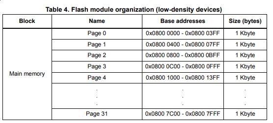
Using that information, it is possible to load the firmware at the specified address (0x08000000 in our case). Using Radare2, it is quite easy :
$ r2 -m 0x08000000 [...] firmware.bin
Unfortunately, Binary Ninja does not have a UI option to change the base address, but it is possible to create a BinaryView plugin to add a new segment and set its base address using a call to add_auto_segment().
Create a new folder in Binary Ninja’s plugin folder (See the documentation) and add a __init__.py file containing the following script :
from binaryninja.architecture import Architecture
from binaryninja.binaryview import BinaryView
from binaryninja.enums import SegmentFlag

class MyView(BinaryView):
    name = "MyView"
    long_name = "My beautiful view"

    def __init__(self, data):
        BinaryView.__init__(self, parent_view = data, file_metadata = data.file)

        #Cortex-M vectors should always be Thumb-2
        self.platform= Architecture['thumb2'].standalone_platform

        #Create a new segment, set the base address to 0x08000000, and read the data file
        self.add_auto_segment(0x08000000, 0x200000, 0, 0x200000, SegmentFlag.SegmentReadable | SegmentFlag.SegmentExecutable)

    @classmethod
    def is_valid_for_data(self, data):
        return True

MyView.register()
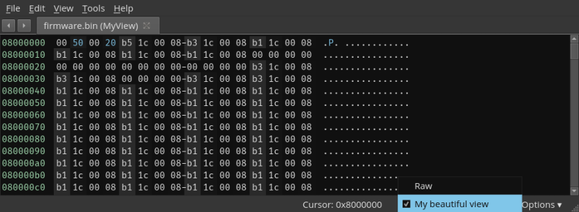
Now, opening a file and choosing My beautiful view in the lower right menu opens the file at the correct address :
Entry point
Contrary to standard executable files, there is no “entry point” in a firmware.
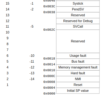
Depending on the MCU architecture, the first instruction location is hardcoded. For instance, the first instruction in an AVR MCU at address 0x0. In Cortex-M family, the first instruction is defined by an exception vector. That vector is documented as the Reset vector, which points to the next instruction to be executed when the device has been… reset. Again, there are multiple vectors, and most of them are manufacturer-dependent. Fortunately for us, the first 16 entries of the vector table are defined in the ARM user guide, and are shared across all Cortex-M family.
Once the vector table has been identified, it is possible to create the reset vector and its function. The following commands entered in the script console will generate the symbol and function for the reset vector :
# Read the reset vector (starting at the 4th byte)
# Note that the LSB is removed since it indicates Thumb-2 instructions
reset_addr = struct.unpack('<I',bv.read(4,4))[0]&~1
# Create the function symbol
bv.define_auto_symbol(Symbol(SymbolType.FunctionSymbol, reset_addr, "f_RESET"))
bv.add_function(reset_addr, bv.platform)
# Tell Binary Ninja that this is our entry point
bv.add_entry_point(reset_addr, bv.platform)
If everything goes well, Binary Ninja will start discovering functions and retrieve most of the firmware functions, but we can do even better.
Peripheral interrupt vectors
As we’ve seen, the vector table can contain many more entries defined by MCU family, which are tied to hardware interrupts. For instance, an interrupt called every time the UART received a byte. Looking at the documentation for that specific chip will help map the vector table to specific IRQs, and help the reverser understand what the firmware does. Let’s take a look at the STM32F103 reference manual again, and on page 204 :
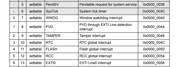
Knowing what these vectors do allow us to better understand the firmware features and discover more functions. We can extract that information from the documentation and build the full vector table.
Automating the task
Getting all the information needed and creating the script specifically for one MCU family is already time consuming. Generating a script for different families might be doable since the manufacturer usually has the same document format, but what about different manufacturers?
libopencm3 to the rescue
From the Github project page, libopencm3 is an Open source ARM Cortex-M microcontroller library, which supports a large number of microcontrollers. The main advantage here is that the API is the same for all supported MCU families, so there is a way to extract all the vector tables from a single source.
Retrieving the base memory addresses
By looking at the codebase, we can see the scripts/genlink.py script, that takes a device database as an input to define compiler flags :
$ python2 scripts/genlink.py ld/devices.data STM32F1 DEFS
-DSTM32F1 -D_ROM_OFF=0x08000000 -D_RAM_OFF=0x20000000
This gives us the flash and RAM base addresses for all supported MCUs in a standard way.
Parsing the vector tables
The vector table is defined at compile time by including include/libopencm3/cm3/vector.h and specifying the MCU family. Here, some bash-fu helps in retrieving the desired values:
$ echo "#include \"libopencm3/cm3/vector.h\"" | gcc -DSTM32F1 -I/dev/shm/libopencm3/include -fno-builtin -E -dD -x c -P - | grep -E "NVIC_\w*_IRQ"
#define NVIC_NMI_IRQ -14
#define NVIC_HARD_FAULT_IRQ -13
#define NVIC_SV_CALL_IRQ -5
#define NVIC_PENDSV_IRQ -2
#define NVIC_SYSTICK_IRQ -1
#define NVIC_NVIC_WWDG_IRQ 0
#define NVIC_PVD_IRQ 1
#define NVIC_TAMP_STAMP_IRQ 2
#define NVIC_RTC_WKUP_IRQ 3
#define NVIC_FLASH_IRQ 4
#define NVIC_RCC_IRQ 5
#define NVIC_EXTI0_IRQ 6
#define NVIC_EXTI1_IRQ 7
#define NVIC_EXTI2_IRQ 8
#define NVIC_EXTI3_IRQ 9
#define NVIC_EXTI4_IRQ 10
#define NVIC_DMA1_STREAM0_IRQ 11
#define NVIC_DMA1_STREAM1_IRQ 12
[...]
Generating all vector tables
Using Python’s class inheritance, we can define a base MCU class which holds the first 16 vectors (common to all Cortex-M) and create subclasses for each MCU family. The base class looks like this :
class MCU(object):
    NAME=""
    ROM_OFF=0x0
    PERIPH_OFF=0x40000000
    RAM_OFF=0x20000000
    IRQ=[
        "SP_VALUE",
        "RESET_IRQ",
        "NMI_IRQ",
        "HARDFAULT_IRQ",
        "MEMORYMANAGE_IRQ",
        "BUSFAULT_IRQ",
        "USAGEFAULT_IRQ",
        "RESERVED",
        "RESERVED",
        "RESERVED",
        "RESERVED",
        "SVCALL_IRQ",
        "DEBUG_MONITOR_IRQ",
        "RESERVED",
        "PEND_SV_IRQ",
        "SYSTICK_IRQ",
    ]
And the following script generates all subclasses for each supported MCU family :
#!/bin/bash

if [[ "$#" -ne 1 ]]; then
    echo "Usage : $0 <libopencm3_dir>"
    exit 0
fi
OCM3_DIR=$1
OCM3_INCLUDE_DIR=$OCM3_DIR/include/

MCUS=( "STM32F0" "STM32F1" "STM32F2" "STM32F3" "STM32F4" "STM32F7" "STM32L0" "STM32L1" "STM32L4" "EFM32TG" "EFM32G" "EFM32LG" "EFM32GG" "EFM32HG" "EFM32WG" "EZR32WG" "LPC13XX" "LPC17XX" "LPC43XX_M4" "LPC43XX_M0" "SAM3A" "SAM3N" "SAM3S" "SAM3U" "SAM3X" "SAM4L" "SAMD" "LM3S" "LM4F" "MSP432E4" "VF6XX" )

for i in "${MCUS[@]}"
do
    echo "class Chip(MCU):" > $i.py
    echo " NAME=\"$i\"" >> $i.py
    python2 $OCM3_DIR/scripts/genlink.py $OCM3_DIR/ld/devices.data $i DEFS | sed -nr 's/-D_/\n /gp' | sed -nr 's/(R[OA]M_OFF)=(0x[0-9A-F]+)/\1=\2/p' >> $i.py
    echo "" >> $i.py
    echo " IRQ=MCU.IRQ+ [" >> $i.py
    echo "#include \"libopencm3/cm3/vector.h\"" | gcc -D$i -I$OCM3_INCLUDE_DIR -fno-builtin -E -dD -x c -P - | grep -E "NVIC\w*_IRQ" | sed -nr 's/^.*(NVIC_\w+_IRQ) (\w+)/ "\1",/p' >> $i.py
    echo " ]">> $i.py
done
Wrapping it up
Using all the tricks above, we created a Binary Ninja plugin that allows us to choose the MCU family, populate the vector table, define their associated functions and let Binary Ninja do its magic. The plugin is available in our Github repo

